
So, yesterday night I finally managed to find the time to work on the stepper drivers configuration.
It turned out not to be as easy as expected, but just follow along!
Polulu A4988
For a first step, just to ensure the RAMPS, Arduino and all of the connectors work, I took the A4988 drivers that came with my RAMPS+Arduino Kit and just inserted those into the stepper driver sockets.
I used my lab bench power supply, which consists of 3 smaller units and unfortunately does only support up to 1A on the 0-20 volt units and max. 5A on the 3rd, 0-6V unit. But with 2 drivers at a time it worked fine and the Polulu’s powered the motors with no problem whatsoever.
Previously, I had set up the Firmware to support the LCD so I moved the motors around directly from that control panel.
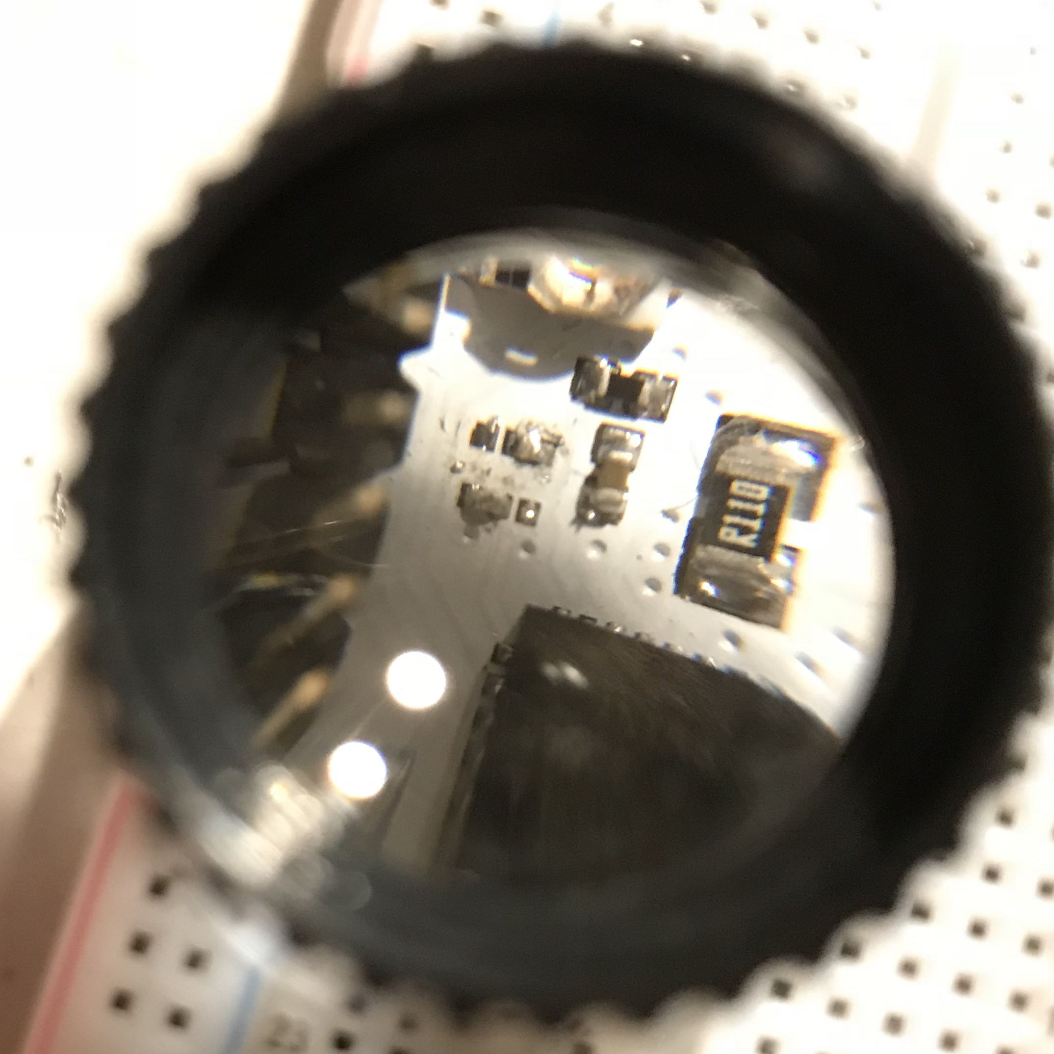
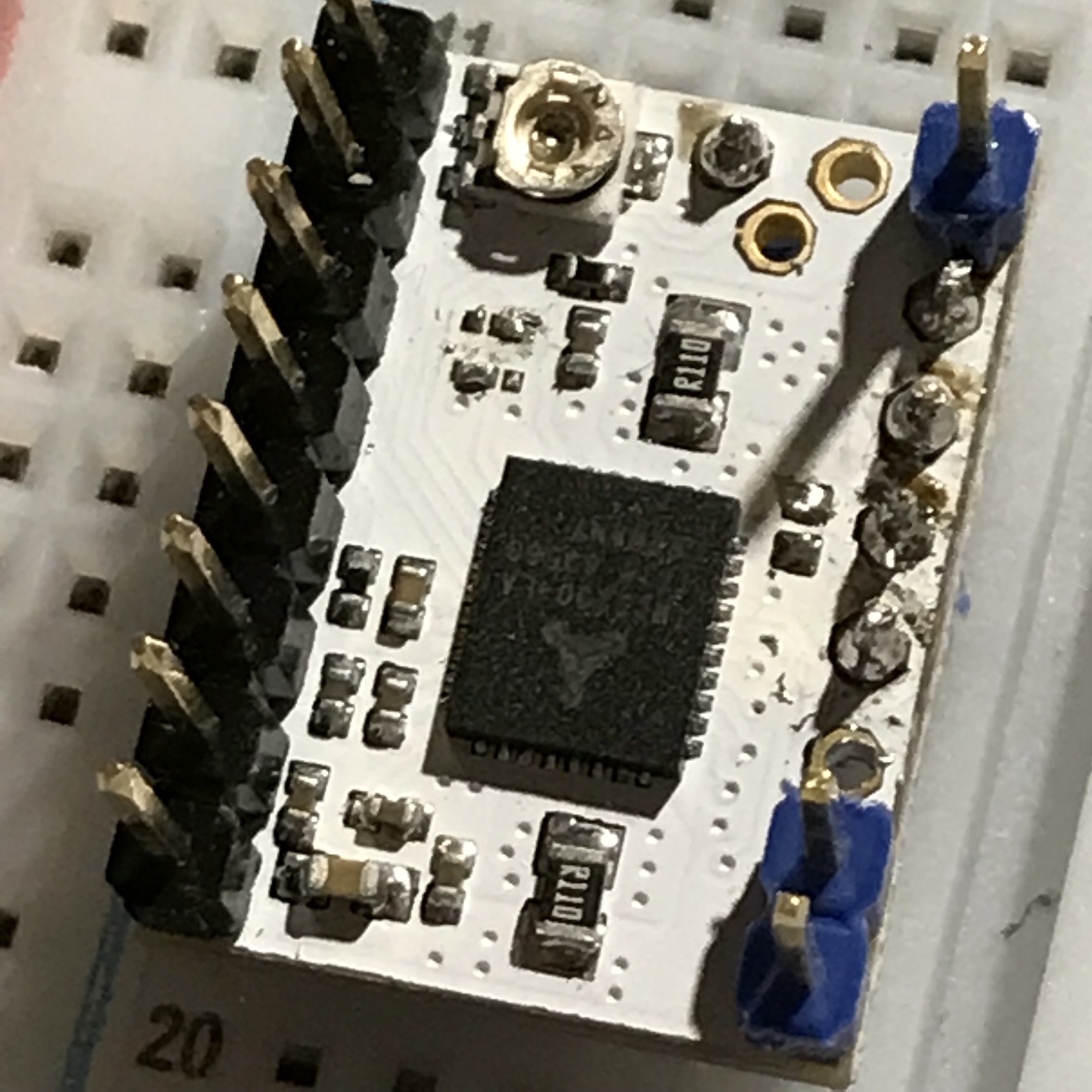
TMC2130
 |
 |
|---|---|
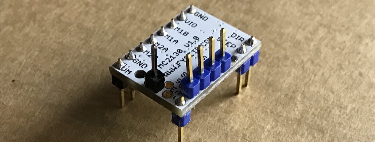
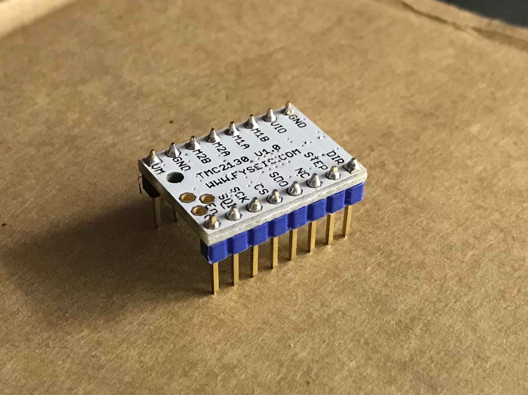
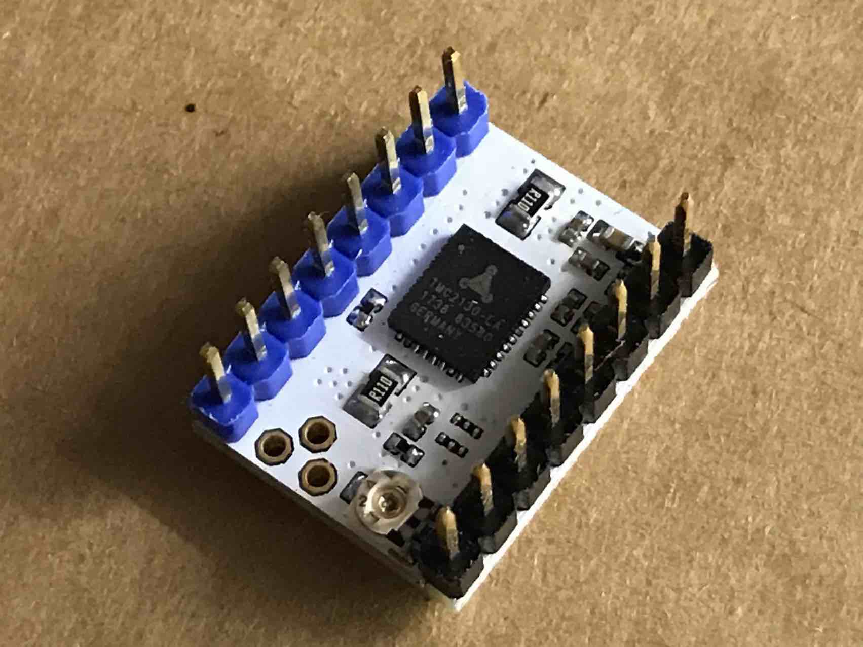
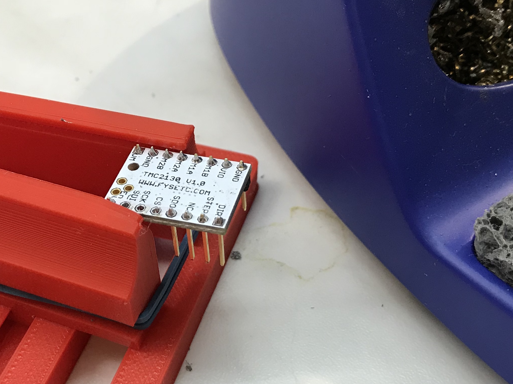
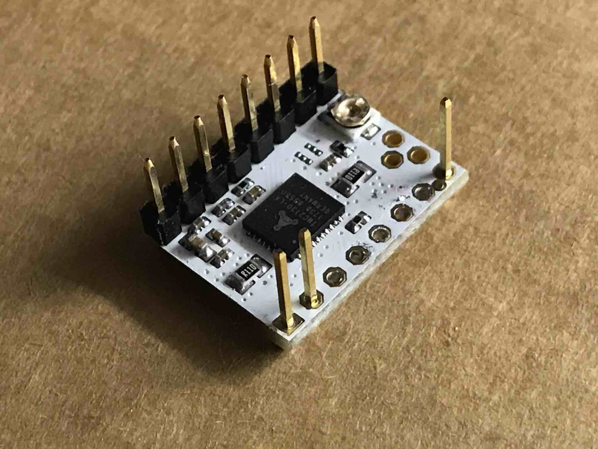
| FYSETC TMC2130 board | Trinamics chip on the bottom, standalone bridge is installed |
Now the tricky part started. I re-read / watched Thomas Sanladerer’s article / video about the topic for the 3rd time and tried to follow along.
Desoldering / Soldering of the Pins
Firstly, in my case the pins were all already soldered, but not in the correct orientations. So instead of just having to solder in a few pins, one side first had to be removed.
 |
 |
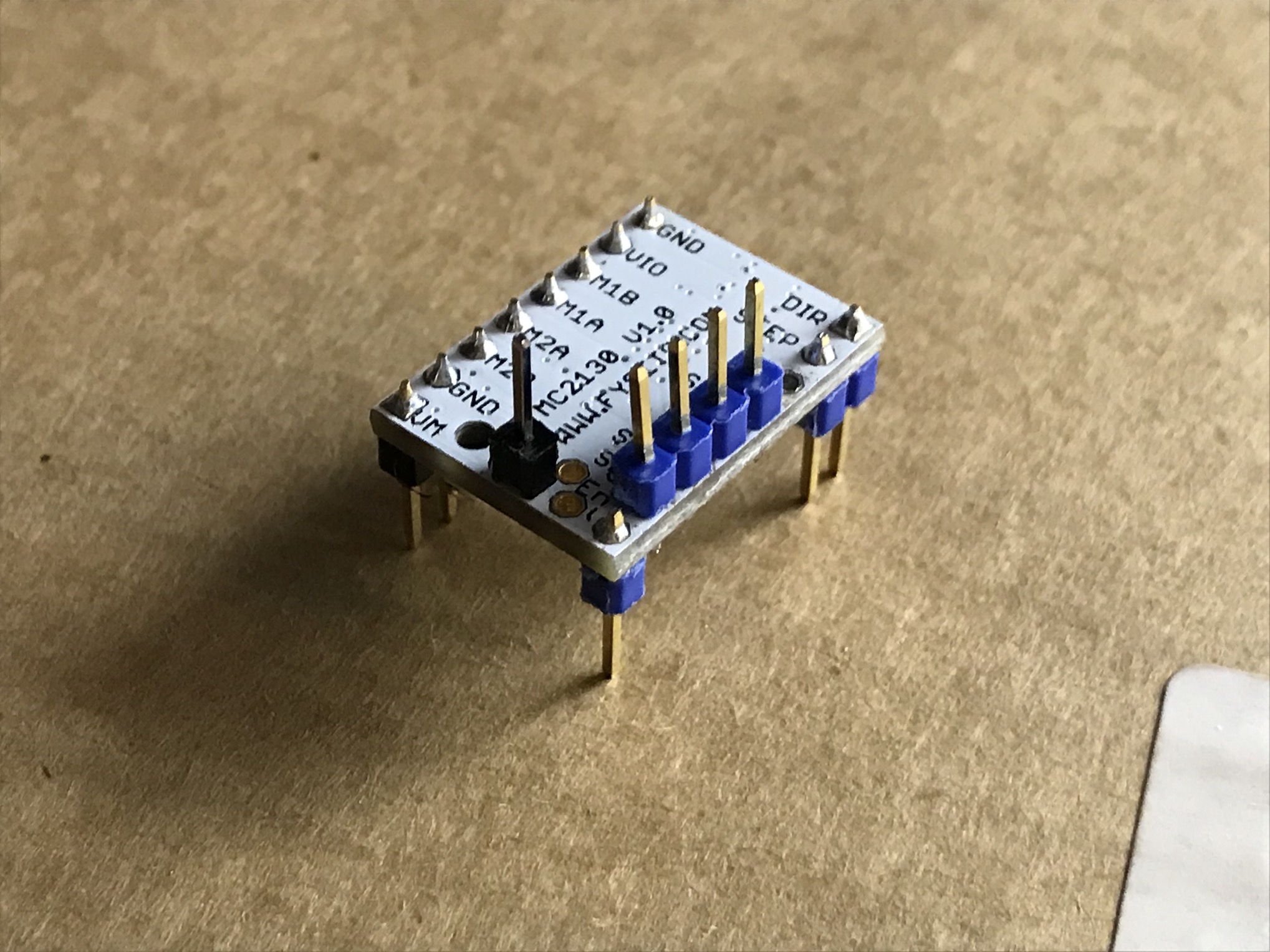 |
There’s a cool trick that makes this easier; just remove the (blue!!) plastic part first and desolder afterwards.
Not only could you melt the plastic, you’ll also save time by not removing the DIR + STEP and the EN pins in the first place.
When that’s done, just solder them back in like shown in Tom’s video and you’re good.
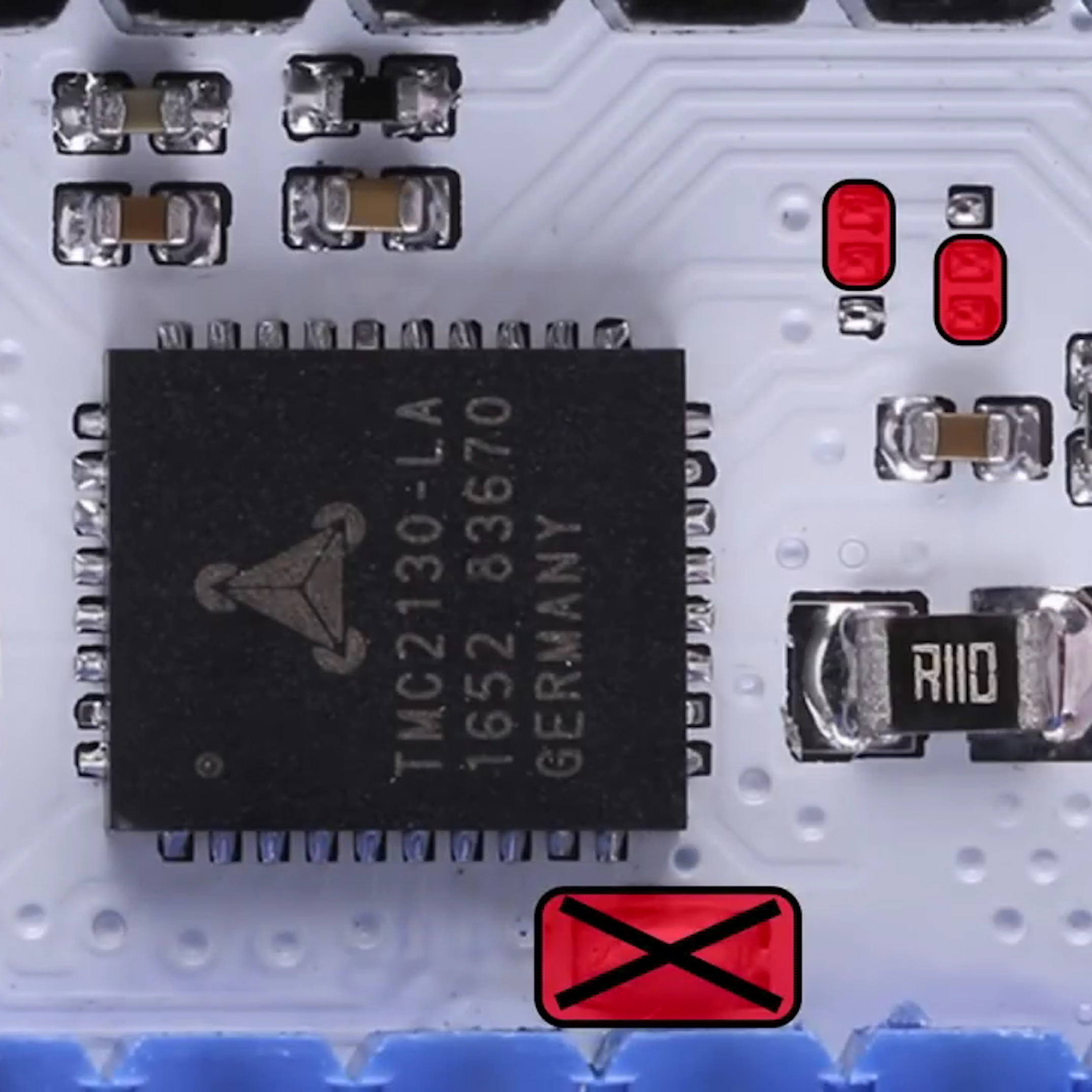
Removing standalone bridge and connect CFG4 / CFG5
This step took me a lot of time to find out; MYtechtips on YouTube explains it very well.
 |
 |
 |
|---|---|---|
| YouTube Screenshot from MYtechtips | Solder Bridges | Solder Bridges + Open standalone Bridge |
If you get genuine drivers from Watterott (which I’d probably suggest now), you can skip this step as they’re already configured like that.
Basically, the FYSETC boards that I got from China are configured to work in “standalone mode”, i.e. without SPI. So you could theoretically just plug them in and they would work out of the box, but without the SPI and thus without all of the awesome configuration options that the chips themselves offer.
You definitely need some kind of lens, a good soldering station and a steady hand as well as some patience for this process. If that’s not for you, just get the original boards.
Firmware Setup
For the firmware, I mostly followed Tom’s video, again. I just added 2 more things that might have been changed in Marlin updates since the video came out and these things can always change in the future, by the way.
The first one is that TMC_DEBUG isn’t enabled by default in the current Marlin version, so you won’t be able to use the pretty important M122 GCODE command later on. It is needed to retrieve information about all of the TMC2130 drivers that you have, like status, max current, etc. and very helpful for debugging.
In addition to that, I uncommented the #define EEPROM_SETTINGS line so that later on I can change the driver’s current and save it to the Arduino.
For more information about EEPROM, this video explains it pretty well.
Testing / Debugging
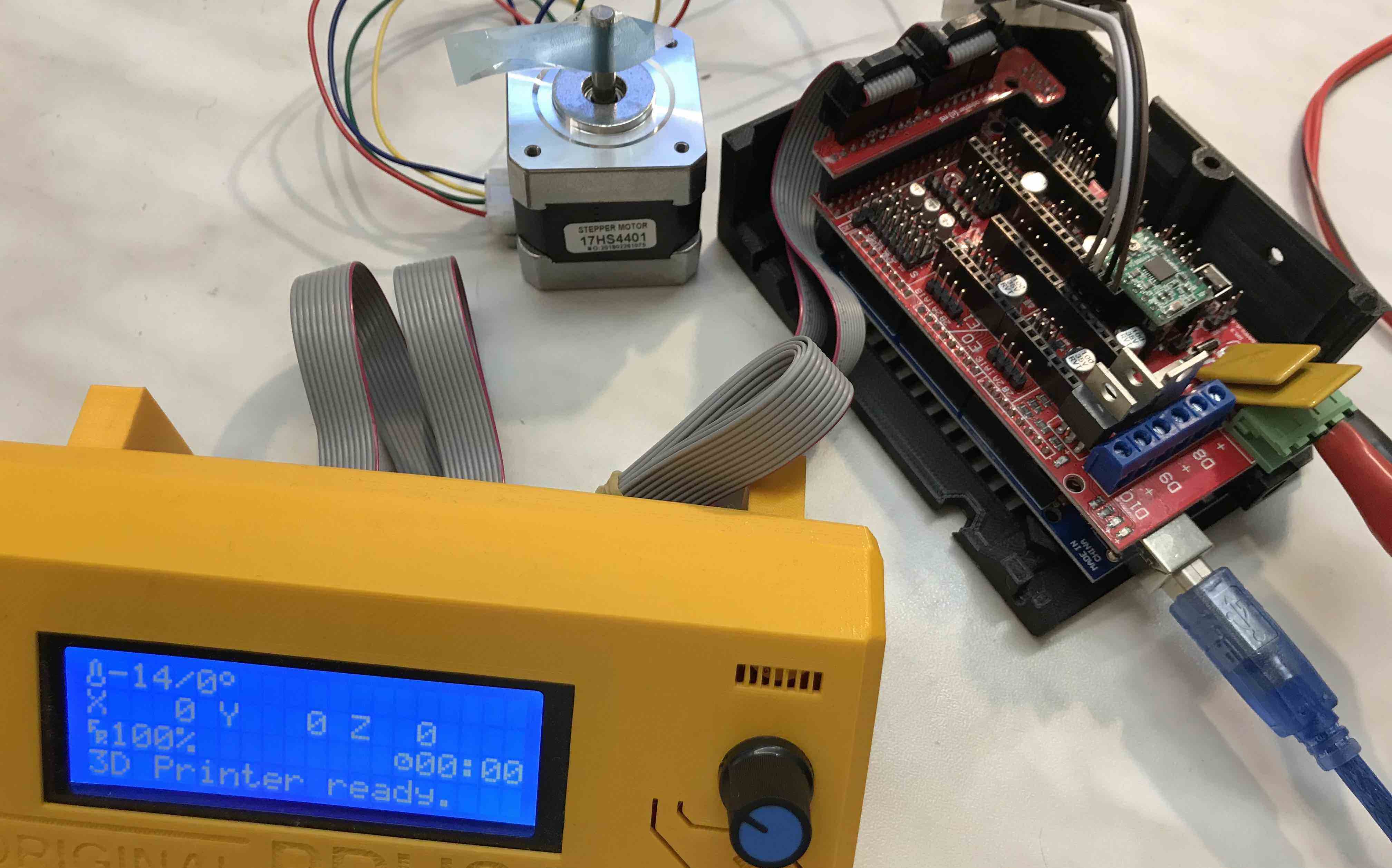
At this point, I was able to move one axis once and after that, all the following G0 commands weren’t doing anything. I tried a lot and even went as far as flashing an “old” version of Marlin (I had a copy / backup from before the TMC configuration) and putting in the “old” drivers just to see if maybe something with the power supply, the motors or the Arduino isn’t fine.
In the end, I asked on Tom’s Forum and it turned out that the stepper current was too high and that I still needed to install my heatsinks because this issue of the drivers shutting down seems to occur when the chips overheat. Adjusting the stepper current is done via M906 X[nnn] Y[nnn] Z[nnn] (where nnn are the values in mA) with a M500 afterwards to save to EEPROM.
The heatsinks can just be sticked on; just make sure to place them right above the chip on the underside and not offset.
Conclusion
- In the end, now I have 2 motors working simultaneously as well as the SPI which is great.
- Homing without endstops works as well (by just holding the spindle), more testing once the printer is assembled.
- If you have Chinese TMC2130 boards, make sure to set them up for SPI.
- Get Watterott boards if you want to save yourself like 2-3 hours of work.
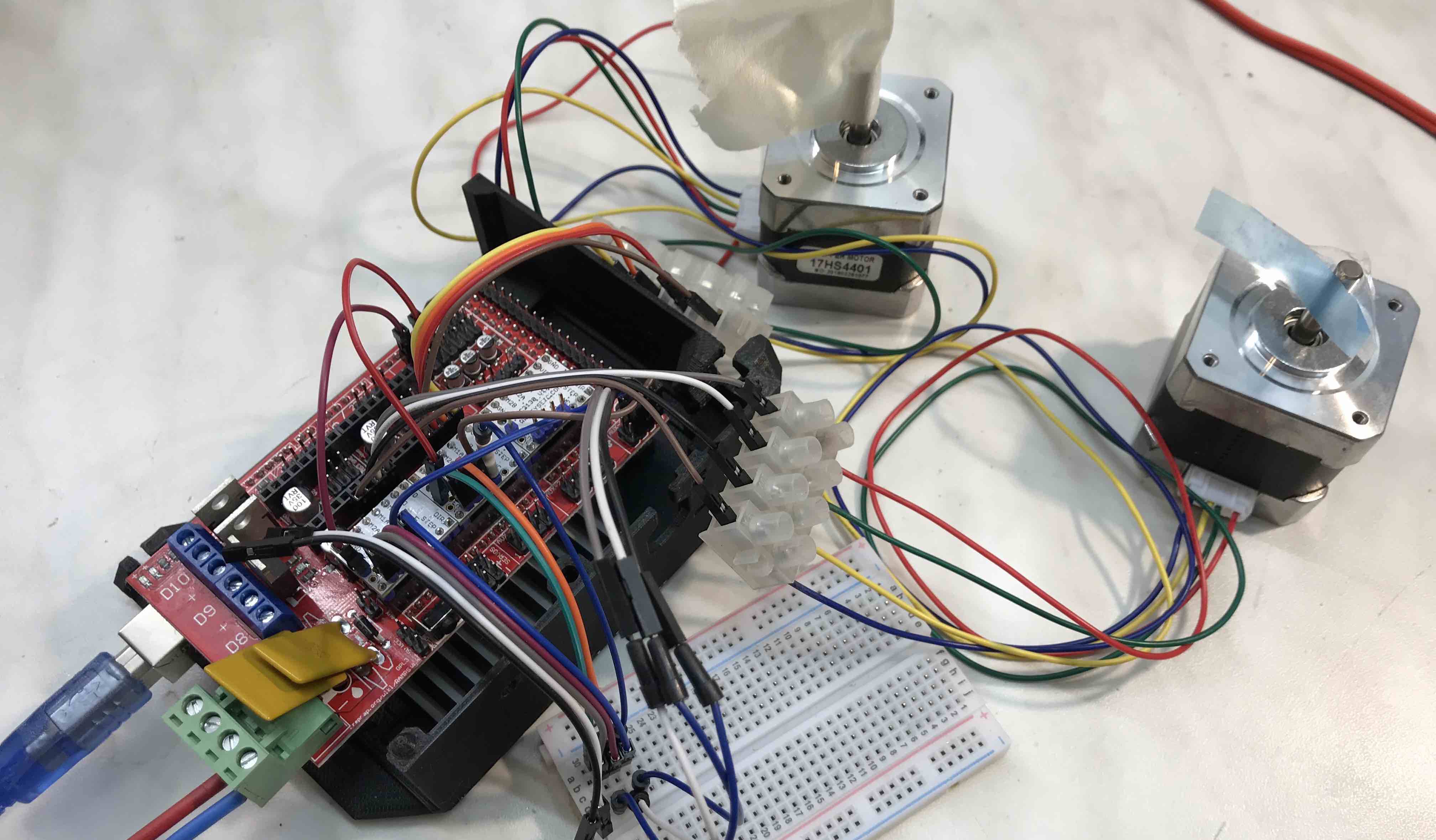
What’s next?
I couldn’t test all 5 motors at the same time, as I need to solder together & crimp both my SPI wires and also make the wires that go from the RAMPS to the motors. You can see in the images that I currently use a clamp that screws the blank leads down to some jumper wires; I didn’t crimp on connectors yet because the cables are too short anyway and I might get some 4-lead cables from the hardware store to make things easier & cleaner.
Also, currently pins from AUX-3 are being used for the SPI communication, which is the exact same spot that the LCD usually connects to.
As far as I know, Thomas (and a lot of other people) do it this way because those pins are configured to be the “SPI pins” per default, and they might not use / need an LCD.
So another next step is to re-map the pins and to get the TMC2130 and the LCD up at the same time 😉
Update (9.7.18): You can now find TMC2130’s on Banggood already set up in the correct way! Here follow 3 alternatives:
- Exactly what I bought from Amazon, roughly the same price but seems to be set up in SPI mode already: no SMD soldering, no swapping of pin directions - link
- Same thing, bundled with stepper driver protector shield. I’ve heard they make sense and think about getting some as well. 1 buck more per driver and you also get some jumper wires. - link
- Very, very cheap alternative, esp. on AliExpress, but I recommend against it. The IC is on the top of the board → cooling won’t work as well as on the FYSETC board (cooling is already an issue with TMC2130). If you still want to try: link
Disclaimer: These are not affiliate links and I haven’t tried any of these boards, but I’m pretty sure that the 2 first ones (FYSETC V1.1) are just what I have, but already set up in the right mode.