
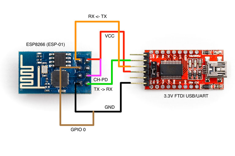
ESP-01 to FTDI-Programmer Adapter
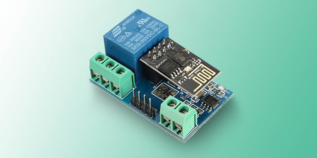
Today, I’ll share my experience (and - spoiler - success 😉) of trying to get a ESP8266 WiFi 5V 1 Channel Relay going.
On one side, I didn’t want to use the pre-loaded firmware because of bugs or security issues that I can’t know about if it’s pre-flashed and on the other side, it just seemed not to work (for whatever reason).
The first issue was the hassle of the jumper cable wiring that needs to be done to program the ESP-01 and having to re-do it every time you test your new firmware (detach all jumper wires and plug the ESP into the relay board).
So, as I like to do that anyway, I pulled out a fresh proto-board from my drawer and some female headers to build an adapter:
 |
 |
|---|---|
| My adapter looks similar to this | These are the required connections needed to be made via jumpers or on prototype board |
Please note that you can totally get away without doing this, but I just found it too annoying to re-plug every one of the 6 jumpers every time and making sure none would fall out of the breadboard in the process etc.
ESP-01 Arduino Sketch
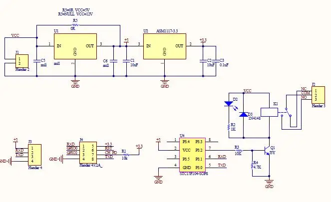
The next thing that was just not documented at all on the product page was how to turn the relay on or off. You might know that you can just buy boards with a relay on them that are toggled by easily driving one pin high or low, which wasn’t the case here. Looking at the schematics, you can also see that there’s another microprocessor on the board in between ESP and relay.
With the help of this great article by John Lindsay and some other bits of info that I had read about the board earlier, I managed to find out that you need to send a few specific byte sequences to the microcontroller over the Serial connection, baud rate 9600.
 |
 |
|---|---|
| Regular relay board, toggled by a single pin | Pinout of my board with STC… microprocessor |
So, here are the most important / bear bones pieces of my Arduino sketch that in practice doesn’t obviously turn the relay on and off all the time (like in this sketch), instead I have a small webserver that allows me to toggle the relay remotely.
Also note, that “on” in my case means the relay is inactive / open (state that it has when turning the whole thing on) and my Pi that should be on 99%+ of the time gets its energy.
Via this ESP relay, I can cut the power by turning the relay “on” and thus turnOff the Pi (that’s why the function names might be confusing).
I also do know that it’s absolutely not good to do this to a Raspberry Pi, but it’s what I need to do anyway (“pull the plug”) when it hangs itself up completely (that does happen from time to time).
bool relayOn = true;

void setup(){
  Serial.begin(9600);
}

void loop() {
  toggle();
  delay(2000);
}

void turnOn(){
  Serial.write("\xa0\x01");	// byte sequence for opening relay
  Serial.write(0x00);		// apparently because of the 0x00
  Serial.write(0xa1);		// you need to send on multiple lines
  relayOn = true;
}

void turnOff(){
  Serial.write("\xa0\x01\x01\xa2"); // byte sequence for closing relay
  relayOn = false;
}

void toggle(){
  if (relayOn){
      turnOff();
  }
  else {
    turnOn();
  }
}
The key points in this second step were the Serial codes (in Hex notation):
A0 01 01 A2 = Close Relay
A0 01 00 A1 = Open Relay
I hope that this article helped clear this 5v relay module up a bit and how to interface with it. Especially since it doesn’t really have a name, I found it very difficult to find a lot of info about it on search engines and the people in the review section of the seller’s website (and a lot of others on blogs) all seem to use either what the boards come with or reprogram in Lua code.
Both solutions weren’t what I wanted, so that’s my kind of way to handle this with a fresh, basic Arduino firmware.
Where to go from that?
Well, firstly as I said I run a very simple webserver on this that lets me toggle the relay and I’ll also try to get deep sleep working on the ESP-01.
As far as I know, it usually isn’t able of doing that, but I’ve seen people do it, so that would be the next step.
Next post will be about my 3DP-progress again!