
RAMPS / LCD Adapter Modification
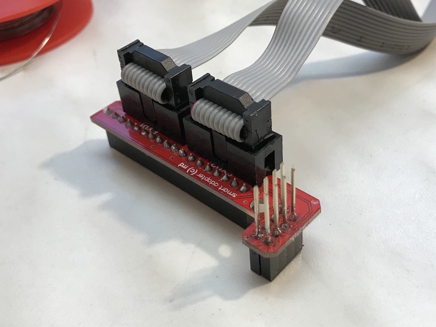
Today, first we are going to talk about a modification of the LCD adapter that allows for a very elegant extension of the AUX3 RAMPS port.
This is always needed if you want to get TMC drivers working together with the LCD, because SPI pins for CLK, MOSI and MISO have to be shared.
- My first attempt was doing something like this; just soldering the shared SPI wires on top of the LCD connector. It took me quite a bit of time and was a real pain. Also it’s not safe at all because you’re very likely to make cold solder joints and / or the joints won’t be strong enough. You could also accidentally short out pins which might damage your board. So I strongly recommend against this procedure. It did work in the end, but I wasn’t happy with the result.
- After a bit of brainstorming - and not “just search on the web - I got this great idea to just use a female header with long pins that are made for going all the way through a board, like on some Arduino Uno shields. This solution is very, very clean, takes less than 5 minutes of work and is completely safe with regards to shorting out pins or something like that.
 |
 |
|---|---|
| First attempt | Second attempt |
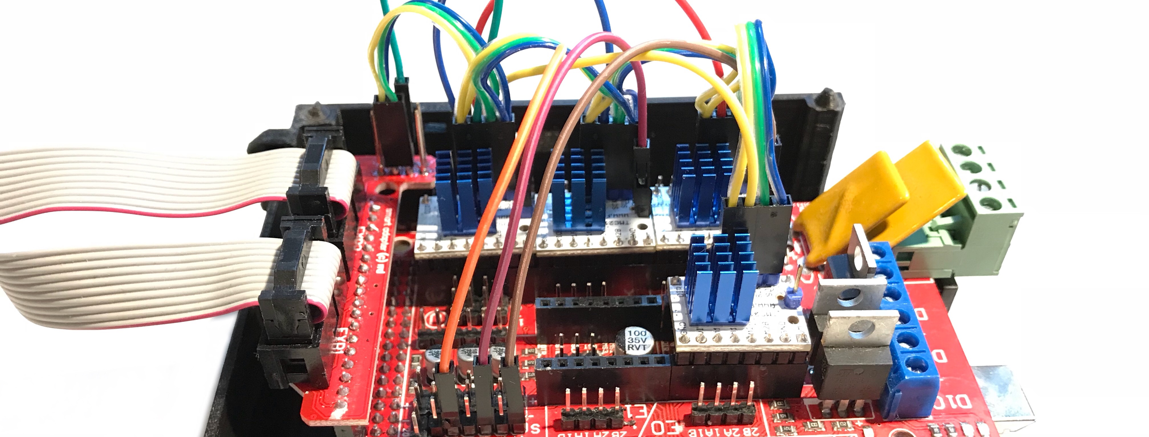
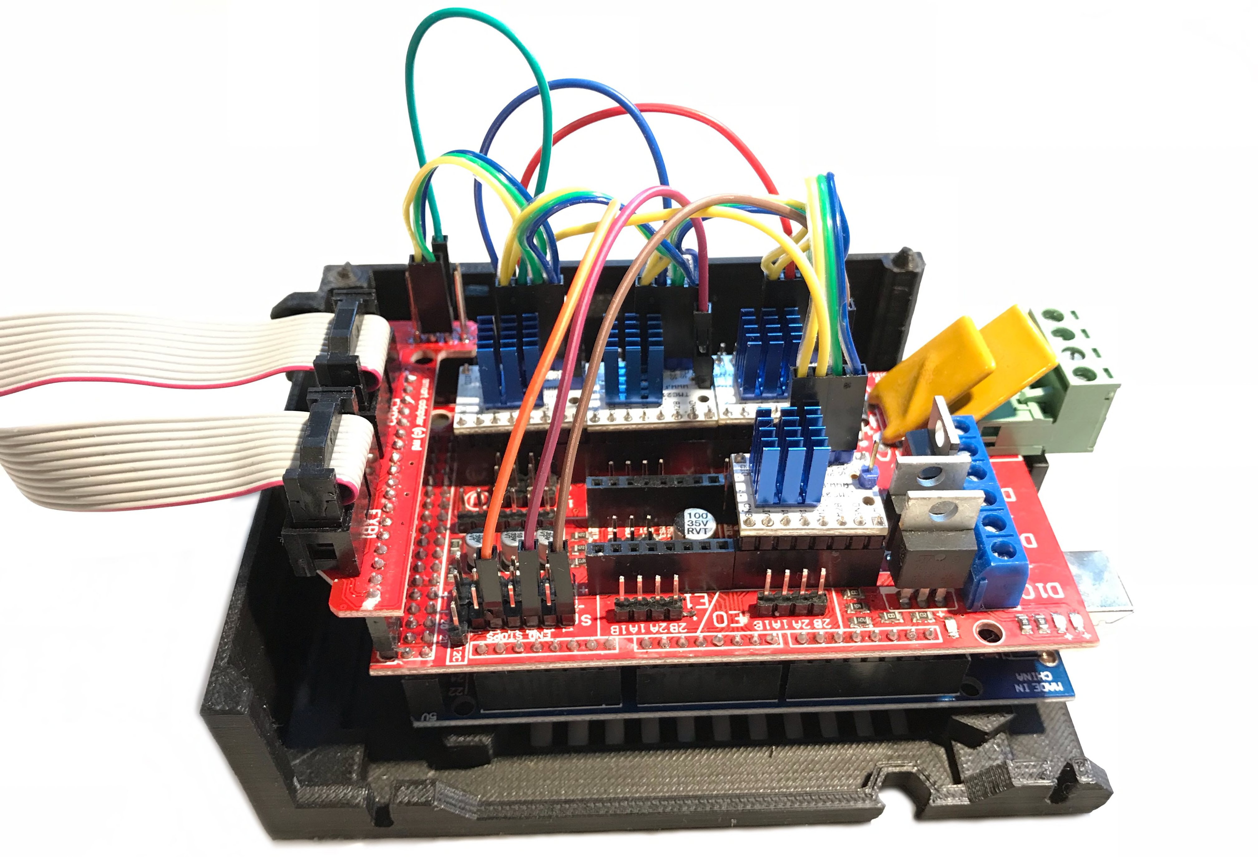
Finishing up TMC2130 Setup
Another thing still on the To-Do List was to make the SPI wiring harness for the drivers. Crimping two wires into one connector is harder than you might think and if I’d have to do this another time, I may do something a little different: Only have one single wire actually enter the connector and join the next wire just a short piece over the connector via a small solder joint.
Anyway, except taking a bit of time and patience this worked out flawlessly. I have a 3 meter roll of wire and a dupont-crimping kit from Banggood that includes male and female cable terminals which served well for this purpose.
I’ll probably also make the motor cables with this method so they’re the exact right length and don’t form loops and hang around everywhere.
 |
 |
|---|---|
| Front | Back |
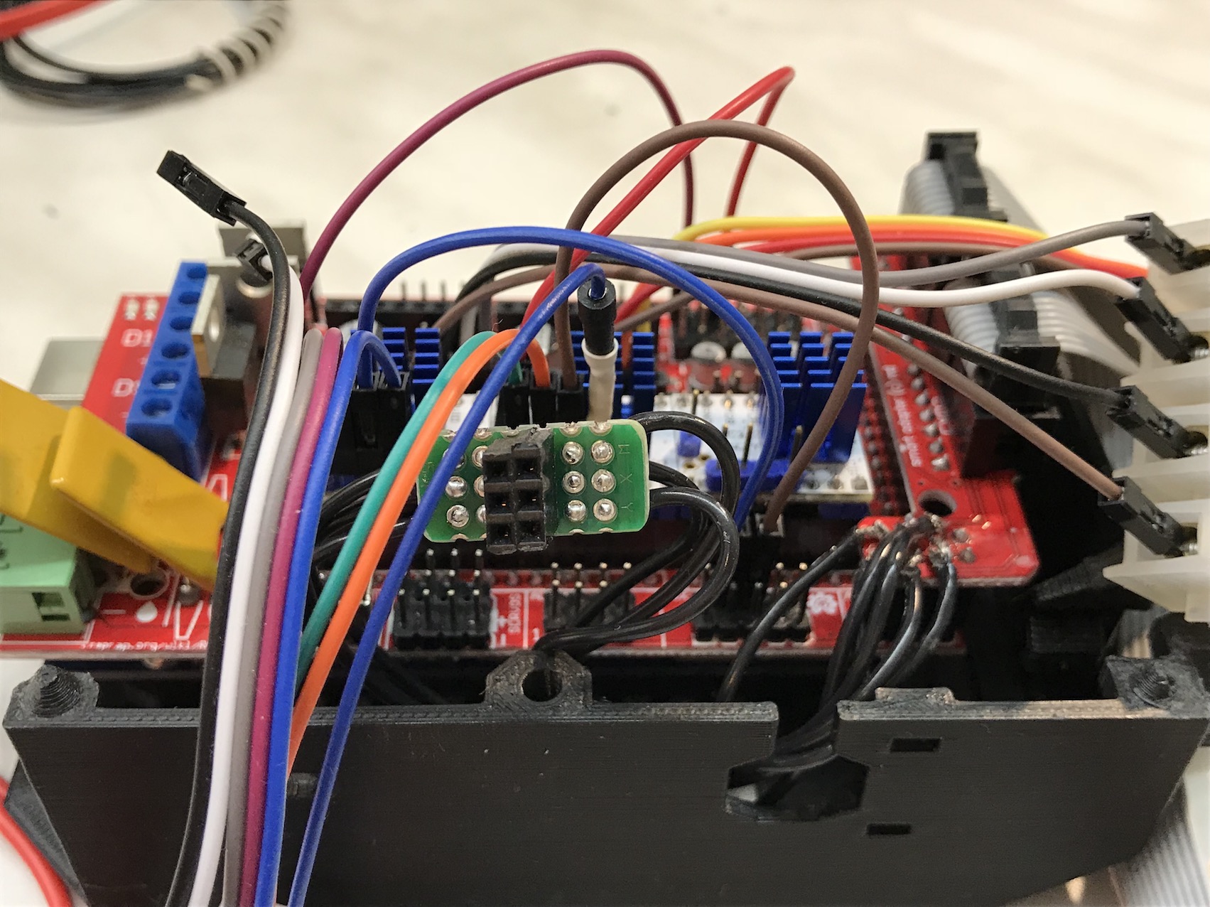
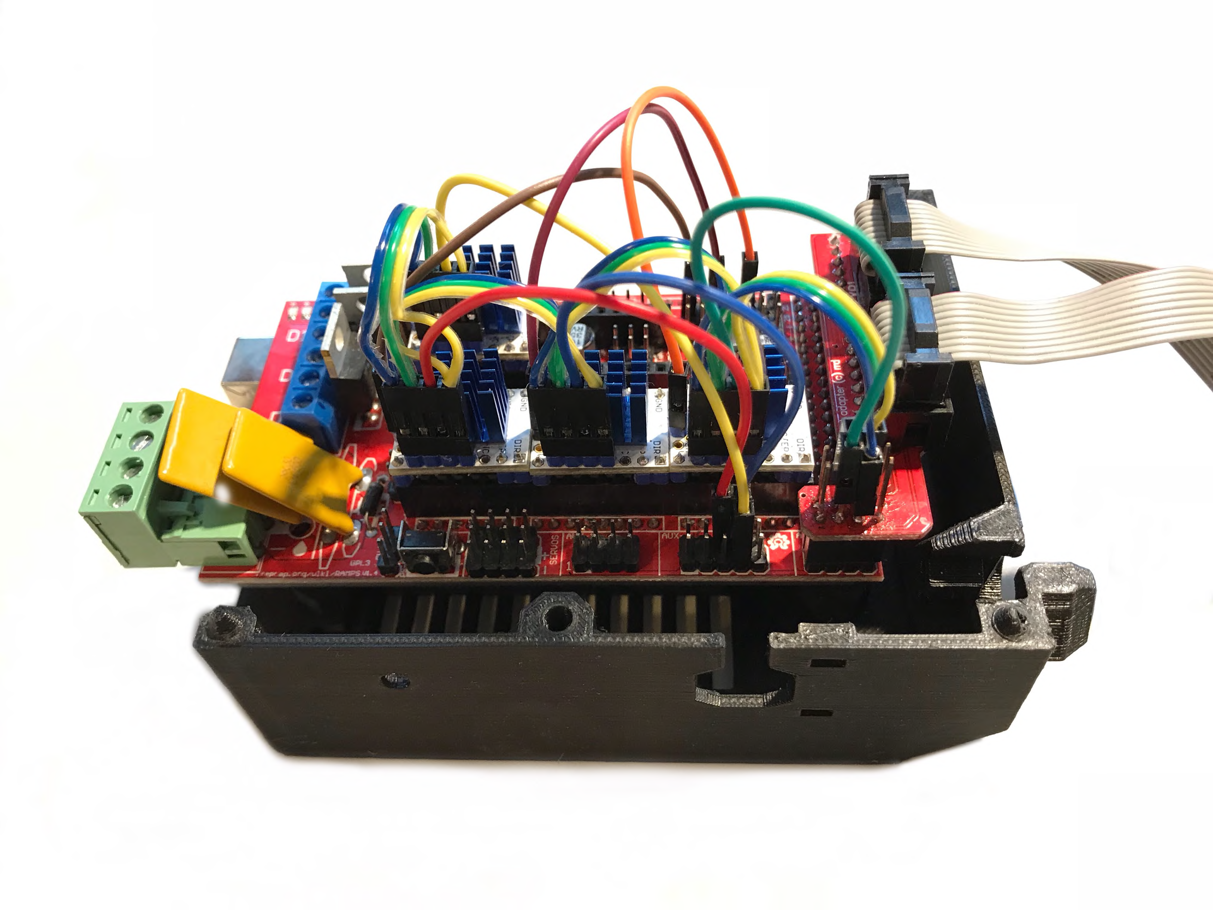
Motor tests
Now, that all drivers are wired up and in place, I could test them (again) as well as all of my motors. I noticed that the Z axis motor didn’t move and just did a high-pitched noise. Research didn’t lead to anything helpful so I played around with the current and other stuff. The socket on the RAMPS as well as the motor were fine, by the way.
Changing the CS pin from 44 to 53 “made” it run, but only in one direction. I’m not sure why, so I just leave it here for documentation purposes. Now, pin 44 is used for E0 (default config) without issues.
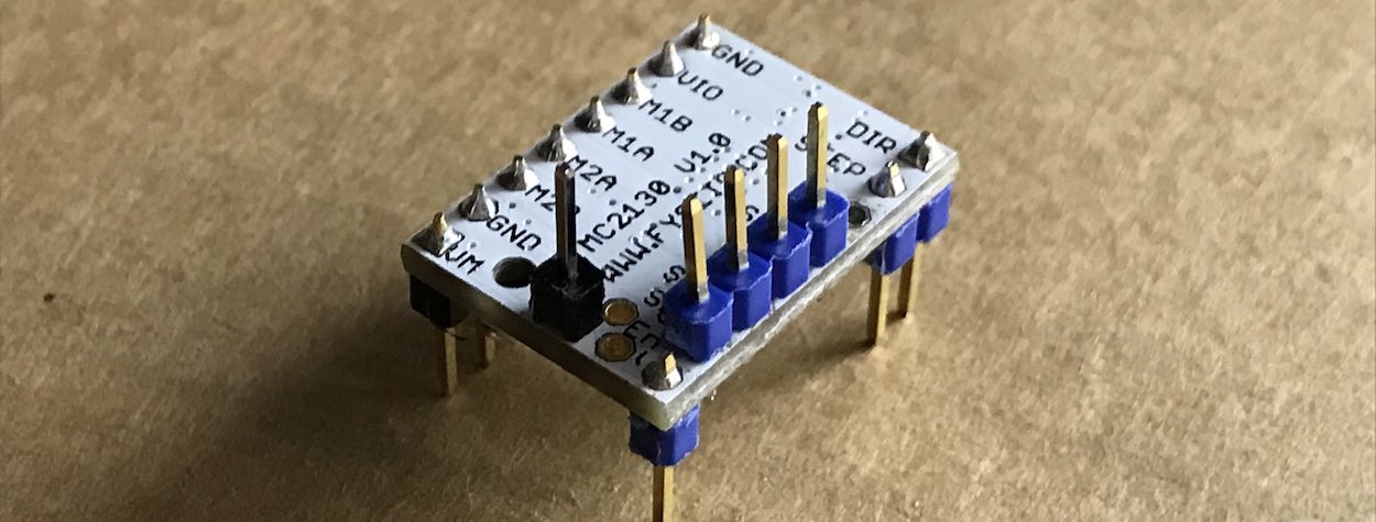
If you know anything about stepper drivers, you’ll be familiar with the fact that the only thing defining the motor direction is the DIR pin. Upon inspection of the driver, I saw that when I had soldered in the pins, a tiny (literally hair-width) bridge had formed between DIR and STEP. To remove it, I didn’t even have to fire up my soldering station; just put a small knife to it and the problem was solved!
So, to recap: Check all of your solder joints if something doesn’t act right!
Another, quickly solved issue was my Z axis revving up like crazy, draining over 1A from my lab bench power supply which cut the power as that’s my usual current max that I set it to.
I didn’t think about the fact that of course, on the Z axis 10mm are a lot more revolutions than on a X / Y axis. Also, it looks like when you move motors from the LCD they use their max feedrate (?) which was simply too high on the Z.
Either do it via GCODE or use the MAX_FEEDRATE setting in Marlin’s Configuration.h file. In my case, I lowered it from 5 to 3 mm/s.
Other small updates
Other stuff that “happened” and I found out in the last month was:
- I received all the wood (Multiplex) that I will need, while unfortunately I couldn’t have it laser-cut or CNC’ed yet.
- The lengths of the Prusa i3 MK3 steel rods aren’t specified in the manuals, so I asked on GitHub - I was linked to zaribo.org that offers the correct steel rod lengths for the MK3 and I’ll probably order them from RepRapDiscount or AliExpress. If you want, you can also get them from the first website, but it’s a lot more expensive as they’re very high quality components by Misumi.
- As I have the Z probe and the MK42 bed, I could do a little test and confirm that they do work well together; of course it’s a 12V probe running from 5V so it’s not as sensitive and it will probably get a bit tricky to get X/Y calibration going. I’ll use a regular Z-endstop in the beginning and work on the sensor part later down the road.
- An excellent resource for
GCODEcommands as well as for information about the TMC2130 drivers (even the FYSETC v1.0 ones that I have!) is Marlin’s own website! It’s very well built and structured and I was surprised to read about the FYSETC boards - finding this resource earlier would have saved me quite some time. - Apparently, AliExpress now also sells MK3 components, whereas in the beginning of this project they only had everything for the MK2. They have the complete frame, even as a kit with aluminium extrusions (already with threads in the corners) and steel rods as well as MK52 heated beds. Of course I’ll stick with the MK42 that I have, also partly because the new one costs double the price and doesn’t include the actual steel sheet, nor does it have any reviews yet.
Up next
- Install the PEI on the heated bed
- Buy / make a Y carriage
- CNC / laser cut / buy the rest of the frame
- Assemble the X-Axis once the steel rods arrive