
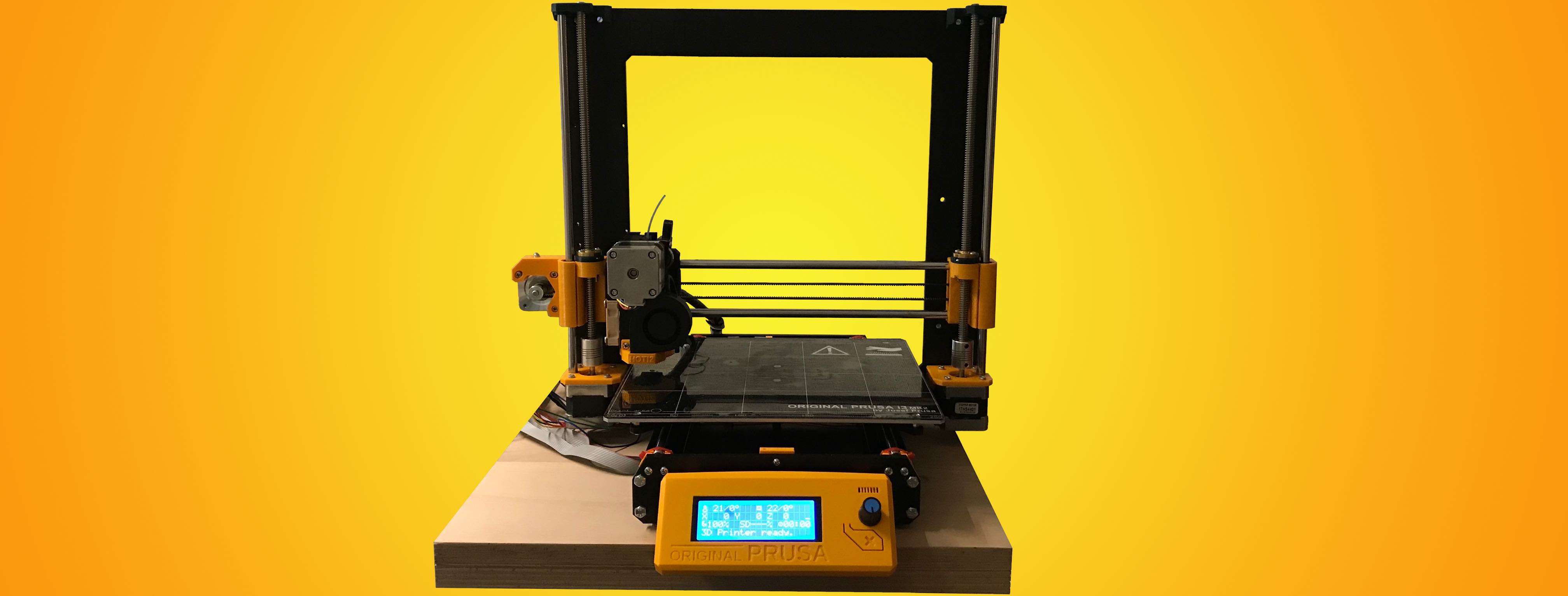
Today I will explain my last few steps that were needed to get the printer up and running / printing. We’ll also discuss the first issues and their solutions as well as the various different To-Do’s that are left.
Extruder test & E-Steps calibration
First of all, the last thing that I hadn’t tested yet at all was the extruder. I had already tested the linear motion on all axes and while the steps per mm weren’t calibrated yet (read later on), no mm of filament had been melted and extruded.
This means that this was also the first real test of the MK2.3 extruder that I chose to use almost half a year ago.
Long story short, the test was a success. The single MK8 drive gear that pushes against a standard 608 skateboard bearing (see my custom extruder idler) grabs the filament well and as it is another frequent challenge to find good springs with the right length and tension (if you’ve got something that works well, contact me and tell me where you got them! 😉), I just screwed the idler onto the filament which seems to work unexpectedly well, too!
The calibration was pretty standard: Mark a spot on the filament 50mm from the top of the extruder body with a sharpie, tell the printer to extrude 20mm (or whichever numbers you prefer and measure from extruder body to the mark to see how much was actually extruded. Then change DEFAULT_AXIS_STEPS_PER_UNIT in Marlin’s Configuration.h file accordingly.
Z-Probe / inductive sensor setup
For the inductive sensor, I’m still not quite happy and will even order a genuine PINDA probe (separate blog post coming up) in hope for better results. The issue that I encountered was that the model that I got has an extremely short trigger distance. It works, but it must be basically the same height as the nozzle. When searching online, I couldn’t find any other probe with a 8mm ‘footprint’ having a longer trigger distance. It’s rated at 2mm and in practice the value is even a lot smaller, most probably because the rated distance is in ‘optimum’ conditions, e.g. the probes are tested against whichever material is best suited to probe.
It was good enough for a few test cubes though which I’m going to talk about later.
What I did was put the printhead to a good height (paper method), then lower the sensor until the little light turns on and then screw it down. Then, shortly after starting the prints I would loosen the screw again and put the sensor in a higher position where it wouldn’t touch the printed part. Of course this was no long-term solution and I came up to the idea to use an other inductive sensor. Turns out that when I first planned this project, I got one from Banggood and - not reading carefully - that thing was 12mm in diameter thus not fitting the original Prusa probe holder, but on the positive side those things are rated at a nice 4mm distance at 6+ Volts. The one that I got works very well at 5V - watch Tech2C’s video: Auto Bed Level Inductive Sensor for 3D Printers for more info about this exact sensor and you’ll learn something about NPN/PNP inductive sensors as well! 😉
To make it fit onto the carriage, I quickly designed a little adapter and printed it on my other 3D printer. This setup works for now, but in the next days I will order an original PINDA (rated at 4mm distance? - I’m not sure) and if it doesn’t work better than my old 8mm probe, I will adapt the X-carriage to fit the 12mm sensor, reprint it and reassemble the whole thing (IKR, what a pain!). At that point, I can also perfectly setup Marlin to use the bed leveling points that the MK42 heated bed offers. On those 9 locations, there are metal inserts that are more conductive and not only enhance the detection distance by the inductive sensor, but should also provide more accurate readings. Luckily, just a few days ago, Chris Riley uploaded a video on this exact subject: MK42 Heated Bed Upgrade - Log - Stock Marlin - Chris’s Basement. I had already tried to setup the leveling to use the 9 points, but it’s not very straight forward and there are a lot of variables and settings in Marlin to control the printer’s bed leveling behaviour, so his video will help a lot.
First test prints and X/Y/Z Steps per mm calibration
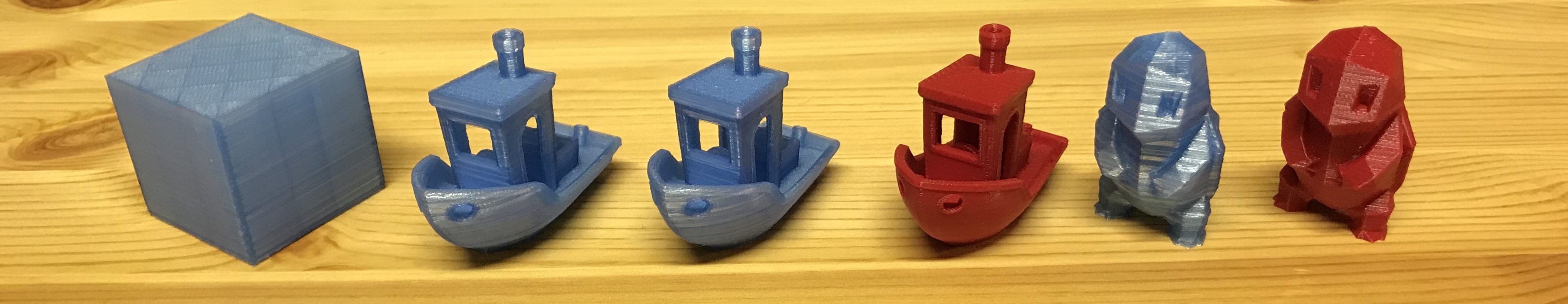
As I mentioned, I still started printing with the “bad” sensor and without calibrating the steps for the different axes. This is why the first few prints were all 10x10mm to 40x40mm cubes. It’s a common method, because the great thing about these cubes is that you do know the dimensions they’re supposed to be and then you measure the real print and compare.
The values that are now working well for me are: #define DEFAULT_AXIS_STEPS_PER_UNIT { 101, 101, 1880 , 120 } with 1.8° per step motors and a lead screw with 2mm lead and 2mm pitch.
I recommend using the Prusa RepRap Calculator for a rough setup and then tune with test cubes until you reach the perfect values. Variations can happen due to a lot of different factors and this setup is one of the most important things - if not the most important one besides a good, level bed (either by a good bed leveling setup or by manual calibration using set screws) - to do on a 3D-printer because we all want dimensional accuracy of our printed models.
Also, the E-Steps should be calibrated first by the method that I explained before, otherwise you might e.g. think that a cube is too large by half a mm because of X/Y-steps while in reality, the axes move perfectly as they should but the amount of extruded material is too much. To further calibrate E-Steps you can also print a cube without infill and without top and bottom layers and then measure if the wall thickness matches the desired 0.4mm.
Real prints, TMC2130 current settings & cooling
My first “real” print is - of course! 😉 - a Benchy. I was very impressed by the smoothness of the surface (even though the filament makes it look much worse than it is in reality), lack of ringing, lack of stringing and great overhangs & details like the steering wheel, chimney etc.
I really think that these properties come from the frame and general structure of this 3D printer, because especially ringing is a typical indication of a frame that is not stiff. Of course, the stringing that I’m kind of used to on my Custom A8 mostly comes from the Bowden setup that I chose to use and the MK3 with its direct drive extruder does naturally not suffer from this artifact. In total, I’d say it just shows again how much Prusa have optimized the original Mendel design from the Prusa Mendel up to this point with the Prusa i3 MK3 which is really great.
One issue that I ran into was layer shifts, so I ended up adding 100 more mA (now running at 750mA each) to both X and Y axis TMC2130 stepper drivers which eliminated the issue. In turn, the drivers started running a bit hotter though, which is why I finally decided to actively cool them with a 140mm PC fan that I got from a Uni friend of mine.
Swapping PLA bushings for LM8UU
On Tom’s 3D Forums I talked with a guy called Stefan who told me he runs his Prusa on 650mA for X and Y, and together with the well audible ‘scratching’ noises that I heard from the PLA bushings and resistance when moving the X axis by hand I decided that while the bushings might be quieter than real bearings, I wanted to try using LM8UU.
To speed up the whole process I just got a pack of 8 from a local seller and got them 2 days later. I’ve installed them on the Y axis, because taking apart the X-carriage is a whole other story (cables everywhere!) and it’s definitely a lot easier to move by hand, so I’ll try to see if I can run the Y axis stepper on lower current now. Of course, this is not just for the sake of having the drivers not overheat but also because somehow bearings are just the ‘right’ way to do linear motion and because I hope for even better prints. One issue with the PLA bushings on a Prusa carriage is that it has only place for 1 bearing / bushing on the right side. This means either you have a really loose PLA bushing (bad for stability of the carriage) or you print one that is a bit tighter but then friction becomes way too large. What I had was a bit on the looser side but the bearings that I have now, feel a lot better. The balance between holding the rod firmly and running smoothly is really good now.
A little tip if you want to get cheap LM8UU bearings: get a couple more so that if one is bad (locking up or something like that), you have spares and maybe the seller will even send you a replacement and you’ll have spares again! 😉
PEI print surface
Last but not least, I wanted to add my experience with the PEI print surface. What I like: The filament (until now only tested PLA) does stick really well, even if the first layer is a little bit too high from the bed and also comes off easily once the bed has cooled back down! Prints sticking ‘too’ well - a thing I’ve heard - is not something I can relate to. My favourite until this day was glass and I always hated that my prints had to be a tiny bit squashed in order to stick well. What I don’t like about PEI: It’s plastic, so it doesn’t protect the actual bed in any way, so you want to be extra careful (!!) when playing around with inductive probe settings & setup. Especially if you have a probe with low detection distance (2mm) and maybe don’t use mesh bed leveling, you also want to make sure your X-axis is perfectly parallel to the heatbed. Otherwise, you might level in the front right corner and then go to print in the center & dig right into the print surface.
This has happened to me, unfortunately but I hope that by sharing my experiences I can prevent you from making the same mistakes. I highly recommend making sure your probe is set up perfectly before you try your first print, even if the process takes you an hour or longer. We’re talking 0.1mm steps (or lower - keyword babystepping) here, so it definitely is a tedious process, but you don’t want to have ‘scars’ and holes in the PEI, because they’ll be visible on the bottom of every succedent print and if you really mess up and don’t react in time I’m also pretty sure that you could warp or otherwise physically damage the bed e.g. damaging the heater tracks (this would be fatal). These things ain’t cheap - more or less 100 bucks if you get the bed from European shops like Zaribo and around 40-60€ from China with a month or more of waiting time. It’s your choice what you buy but it’s a lot of money and / or waiting time for a comparatively small mistake.
As mentioned a few paragraphs above, the surface is so sticky that it doesn’t matter if your first layer is a little bit too high. You can also compensate by increasing ‘first layer width’ / ‘first layer extrusion multiplier’ or however this kind of feature is called in your slicer that just increases the extruder feedrate for the first layer.
If you use a MK42 heated bed, definitely watch the previously linked video MK42 Heated Bed Upgrade - Log - Stock Marlin - Chris’s Basement by Chris and set up Marlin to use the 9 bed leveling points and level the bed before every print. I played around a bit with the 8mm probe (2mm rated detection distance) and it turns out that on these spots the probe can be around 0.6mm higher than on the rest of the bed and still read them. This is great, because essentially it’s an extra 3 layers of clearance between probe and printed object.
As a conclusion, I think you might want to get the MK52 heatbed because of the increased strength and resistance to scrapers, blades etc. (the PEI sheet option that I have also scratches very easily by the way!) in addition to the convenience of taking the printed objects off by warping the steel plate. On the other hand, if you don’t really need this feature, can live with a not-forever-perfect print surface and maybe change it once a year for a few bucks as well as calibrate your printer well, you can save around 50 bucks which can be a lot of money. Get yourself a few spools of filament for example!
To-Do
- What I still want to do is first of all to figure out what my final probing setup will be. Since I’ve started writing this article, I’ve found out that the PINDA probe also only has a 2mm detection distance, so it seems to essentially just be a glorified LJ8A3-2-Z/AX.
- Set up mesh leveling as I’ve now said multiple times, especially to use the probing points on the MK42 heatbed and enable live Z-adjustment.
- I need to clean up the wires from the stepper motors using zip-ties which is very well documented in the manual, I just didn’t get to do it but the printer will look a lot cleaner and be safer against cables getting pulled out by accident.
- Find or design an appropriate electronics enclosure and print it (original doesn’t fit because the TMC2130 with their wiring harness take up too much space).
- Print a PSU cover and install the PSU on the printer with a fused switch.
- Swap the X-Axis PLA bushings with LM8UU bearings.
- Reprint remixed
z-axis-top.stlparts in the correct color.
First conclusions and takeaways / lessons learned:
- The Prusa i3 MK3 frame is a really nice base for a 3D printer, stiff enough and the printer footprint to print volume ratio is great. Get one out of Aluminium imho.
- You can get a lot of parts from China and they’ll be quite good quality for the low prices that you pay. Often, I think what you buy locally or e.g. on Amazon is exactly the same stuff and you just pay the premium for faster shipping time. But if you can wait, you’ll get the same stuff a lot cheaper.
- Especially the heated bed was a positive ‘surprise’ for me. It heats up quickly, evenly and I do like the PEI if the printer is configured properly.
- Be careful before you order and don’t get the wrong parts! It happens. 😂 Be extra careful when it comes to the more expensive parts like: heated bed, Noctua fan, E3D V6 - they’re all available for 12V and 24V systems!
- I would stick to the standard 12V. My PSU outputs ‘only’ 20A at 12V and the extruder heats from 20°C to 200°C in under a minute, the heated bed from 20°C to 60°C in around 2 minutes.
- E3D (or cloned) hotend socks are great! I haven’t talked about them yet, but I have to say I love that thing. Filament doesn’t stick to the block / fall down while printing and comes off easily and without residue from the sock when priming the nozzle before a print.
- Don’t print the original
x-end-idler.stlandx-end-motor.stlfiles unless you have original T-nuts (or explicit clones like from AliExpress), as the normal ‘golden’ leadscrew nuts don’t fit these parts. There are remixes on Thingiverse which should work! If it’s ‘too late’ there is this 22mm to 25mm Lead Screw Nut Adaptor that I also use. It works well. - Building / buying an adapter for switchable hotend fan is not really needed as the fan is so quiet that it might just be a possible failure vector. Not sure if I’ll keep using it. Of course, the lifetime of the Noctua is increased if you use one.
- Don’t use PLA bushings, just get a pack of 12 LM8UU bearings for 10 bucks.
- Get TMC2130 drivers where the pins are already soldered in the right way and the board is set up in SPI mode.
- Try to get an LCD with a low profile potentiometer if you want to use the original knob (minor thing tbh but worth mentioning).
- You can print all of the parts in PETG without issues as long as you don’t print ABS with the MK3 - haven’t tested that!